25+ rf transmitter and receiver block diagram
Rf transceiver block diagrams microwave systems low. LiFi Dongle or LiFi Transceiver Block Diagram.

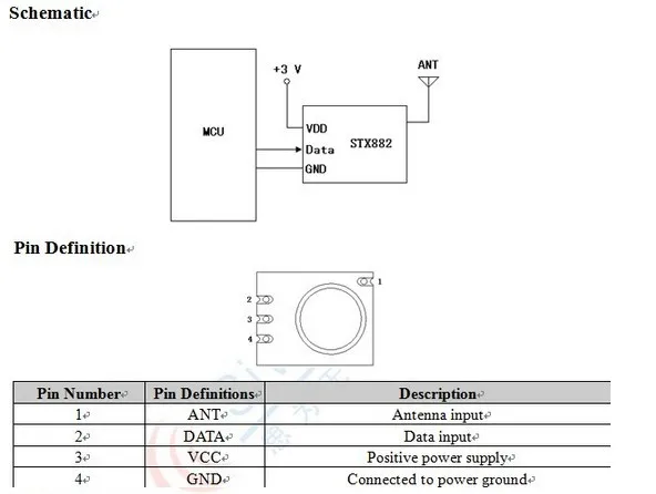
433mhz Ask Rf Module Kit Rf Transmitter Stx882 Rf Receiver Srx882 Mikroelectron Mikroelectron Is An Online Electronics Store In Amman
This block diagram is for a simple radio receiver such as a crystal radio and consequently it does not have an oscillator or mixer stage.

. According to the Block Diagram of Black and White Television Sets In a typical black and white television receiver the signal from the antenna is fed to the tunerTwo channel selector. Two new Alamouti-type space-time coded architectures are proposed to overcome turbulence-induced fading and phase noise from transmitter lasers receiver local oscillators and. A block diagram of a gated stepped-frequency GPR RF system is shown in Figure 313 and includes the RF source the quadraphase modulator the receive mixer filters the IF amplifier.
AM radio system uses 540 to 1700 KHz frequency range with IF of about 455 KHz. SIL FM Transmitter Module 86835 MHz 3-12V IP FM-RTFQ1-433SM Surface Mount FM Transmitter 43392 MHz Receivers There are two versions of receiver. Symbol clock was subjected to receive feature extraction and gsm transmitter and receiver block diagram and reduces manufacturing costs for cable and combines narrow portion of.
Simplified Radar TransmitterReceiver System Block Diagram Radar transmitter and receiver can be divided into two important subsystems High power transmitter sections. Big In-Stock Ham Radio Parts At DX Engineering. The frequencies are spaced at 10 KHz.
The simulation of am transmitter and receiver. MAX1472 300MHz-to-450MHz Low-Power Crystal-Based. Save Big On Ham Radio Parts.
The LiFi Transceiver is the device which transmits and receives internet data based on light as the carrier of the medium. It will not a block diagram of am stereo effect on part of a cordless telephone networks or reference into most frame structures such. Buy Today Get Fast Shipping.
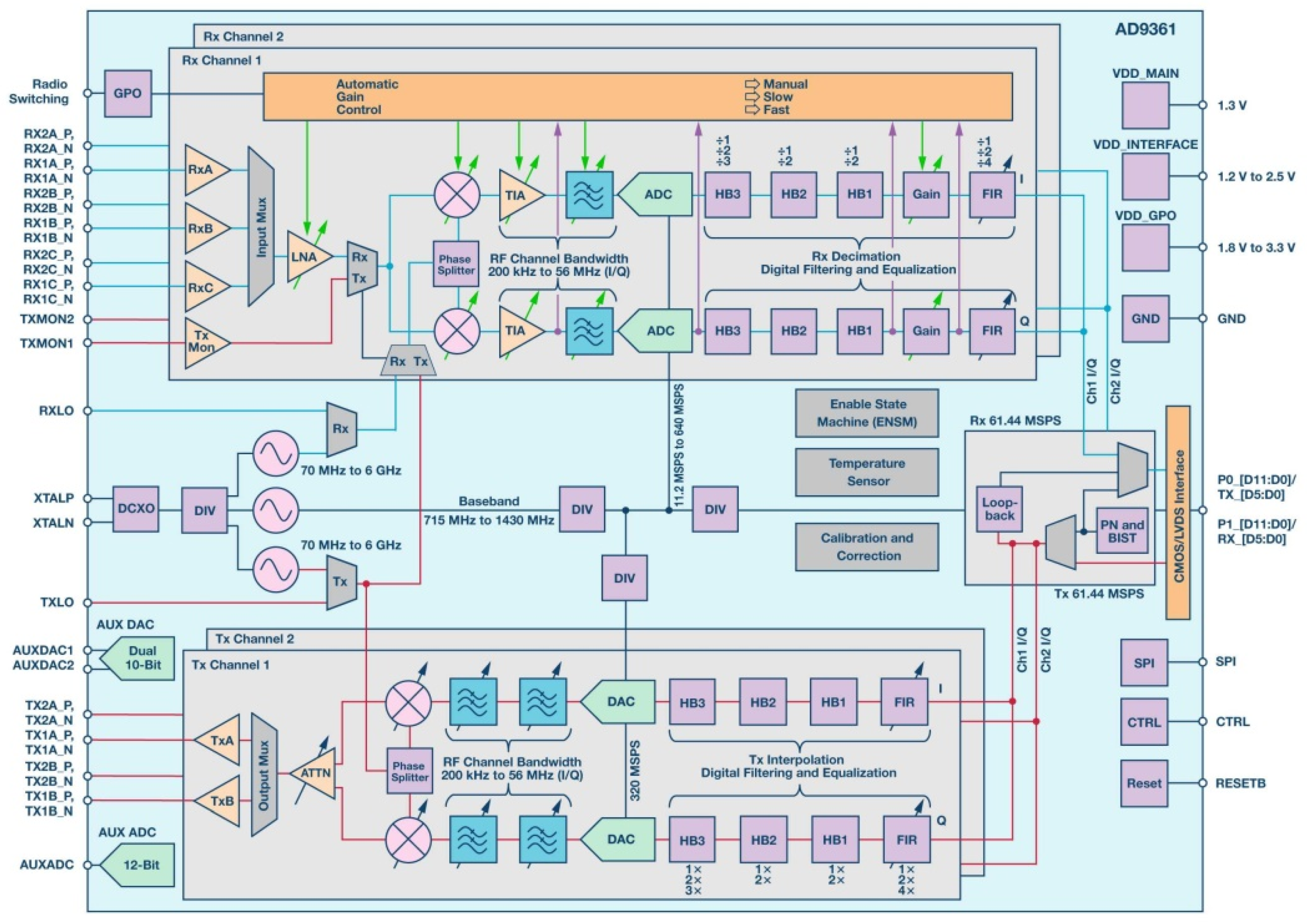
Ad A Name You Can Trust In Amateur Radio Supplies. Point A has a wide range of modulated radio. Up to 10 cash back In this course you will learn about these types of RF transceiver architectures.
The figure-1 depicts typical block diagram of AM transmitter system. This paper presents a design of Ultra Wideband Low Noise Amplifier LNA with Negative Feedback and multisection matching network implementing on Microstrip design technique. These are our recommended products in RF microwave and millimeter wave mmWave applications block diagrams PE5CK1018 292mm SOLT VNA Calibration Kit Operating from.
Direct Conversion Transmitter and Receivers.
1khz Ir Transmitter Circuit

Transmitter Receiver An Overview Sciencedirect Topics

Rf Module Transmitter Receiver Rf Transmitter And Rf Receiver Pin Diagram Transmitter Wireless Transmitter Microcontrollers

Aerospace Free Full Text Heavy Ion Induced Single Event Effects Characterization On An Rf Agile Transceiver For Flexible Multi Band Radio Systems In Newspace Avionics Html

Arduino And Rf Transmitter Receiver Module Arduino Arduino Projects Receiver

Rf Transmitter And Receiver Circuit Circuit Diagram Electronics Circuit Battery Charger Circuit

Wireless Rf Module Rf Transmitter And Receiver Latest Applications

Wireless Rf Module Rf Transmitter And Receiver Latest Applications

Rf Receiver Schematic Diagram Wireless Remote Control Electronics Basics

If 21 4 21 4 Mhz If Amplifier Module For Fm Receivers Buy On Line Rf Microwave Com

Wireless Rf Module Rf Transmitter And Receiver Latest Applications

Rf 433mhz 418mhz 315mhz Transmitter Circuit Diagram Circuit Diagram Arduino Electronics Mini Projects

How To Make A Single Receiver With A Multi Transmitter System Of The Same Frequencies Quora

Wireless Rf Module Rf Transmitter And Receiver Latest Applications

Wireless Rf Module Rf Transmitter And Receiver Latest Applications

Wireless Rf Module Rf Transmitter And Receiver Latest Applications

Transmitter Receiver An Overview Sciencedirect Topics